David R. Nutt and Anthony J. Stone
J. Chem. Phys. 119, 5670–5679 (2003).
© (2003) D. R. Nutt and A. J. Stone and the Journal of Chemical Physics
Click on an image to see an enlarged version. Please see the published paper for detailed captions and discussion.
The figures were drawn using Molscript and Xfig and prepared for the web using Gimp.
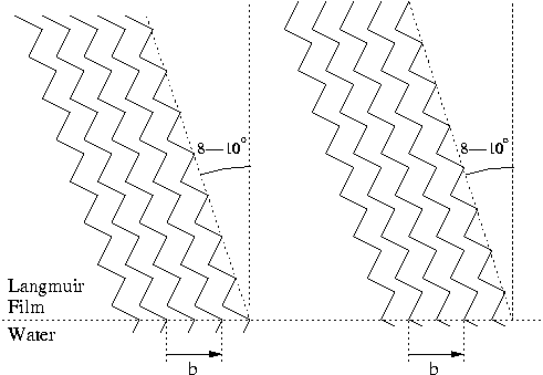
Figure 1: The two possible packing arrangements of
aliphatic alcohols in a Langmuir film.
Figure 2: Exploded view of the head group orientation
resulting from the two possible packing arrangements.
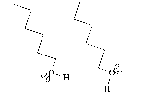
Figure 3: Labelling of atoms and orientation of axes of the
ethanol molecule.
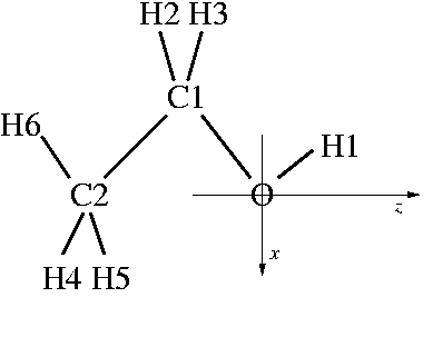
Figure 4: Optimised geometries for the
ethanol--water complex from MP2 calculations and using the model
potential.
(a) 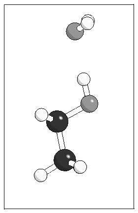 (b)
(b) 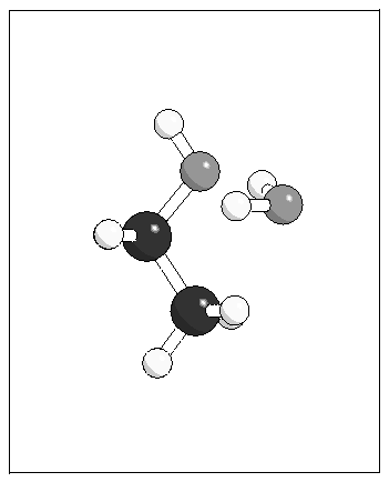
(c) 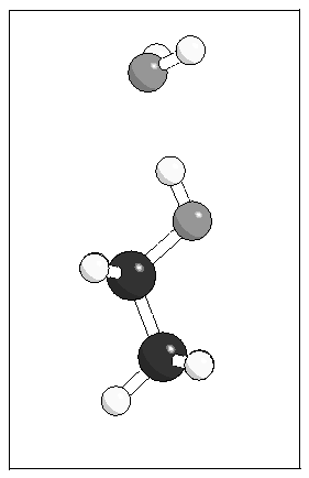 (d)
(d) 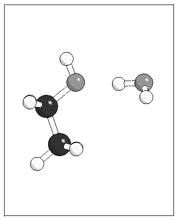
Figure 5: Structure of monolayers A and B. The direction of
the tilt of the molecular axis is indicated by a "T" and the direction
of the O--H bond by an "H".
(a) 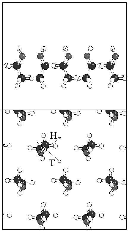 (b)
(b) 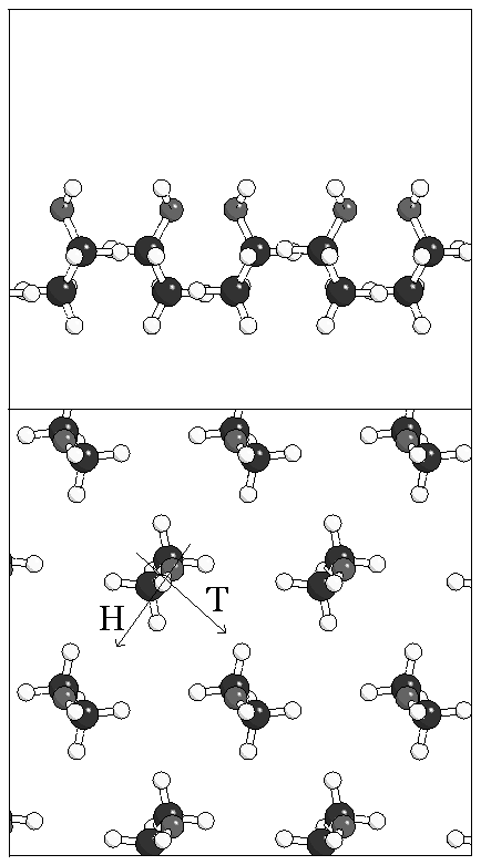
Figure 6: Minimum energy geometries for a single water
molecule adsorbed on monolayer A.
(a) 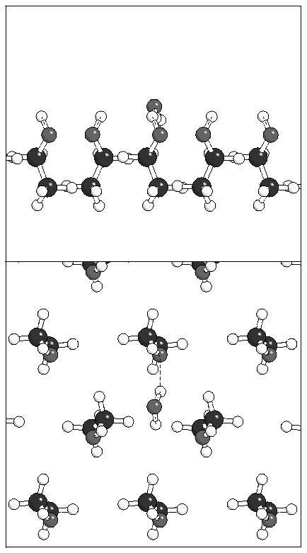 (b)
(b) 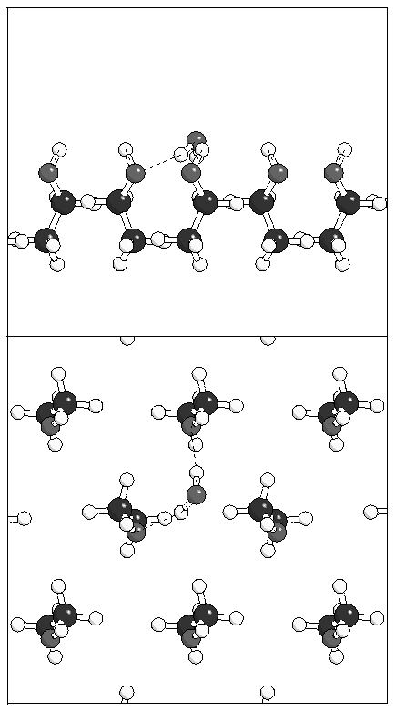
Figure 7: Clusters of 3 and 4 water molecules on monolayer
A.
(a) 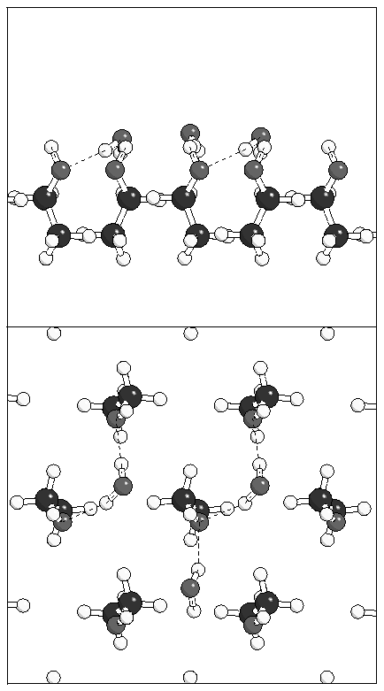 (b)
(b) 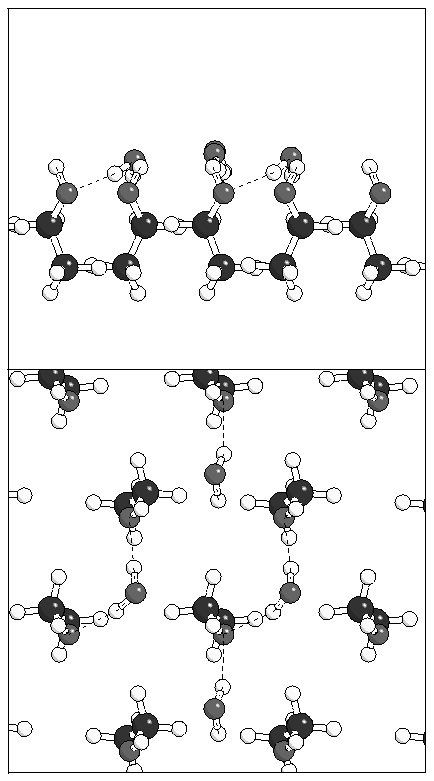
Figure 8: Minimum energy geometry for a water monolayer on
monolayer A.
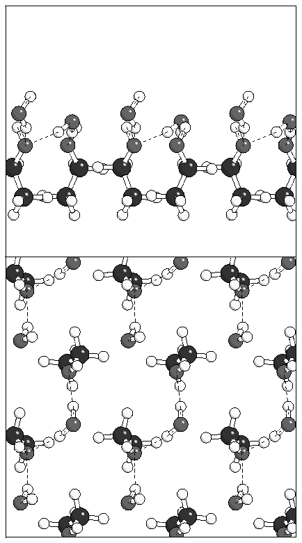
Figure 9: Three possible ice structures which could be
built on the alcohol monolayer.
(a) 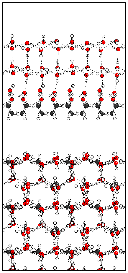 (b)
(b) 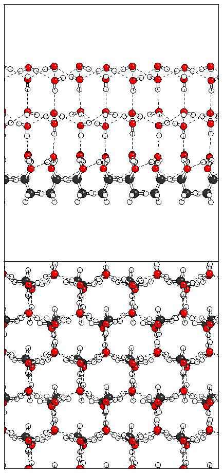 (c)
(c) 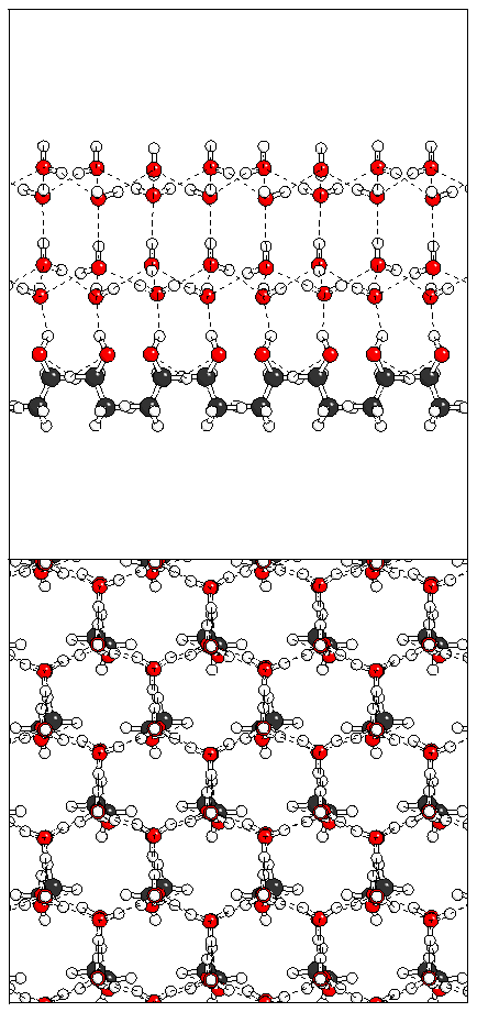
Figure 10: Relaxation of the odd ferroelectric heptalayer
structure.
(a) 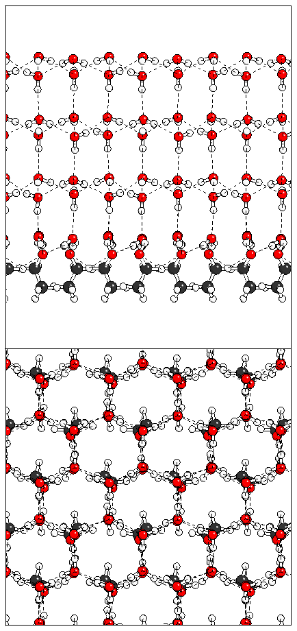 (b)
(b) 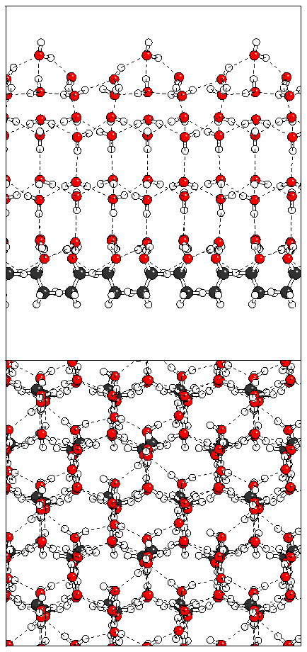 (c)
(c) 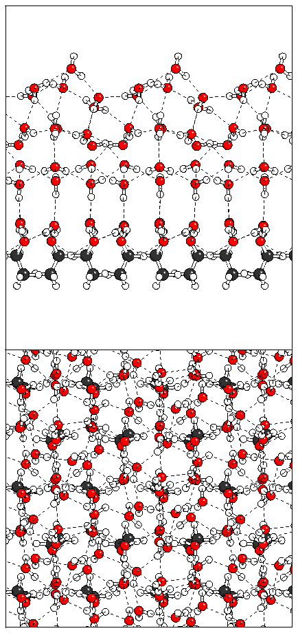 (d)
(d) 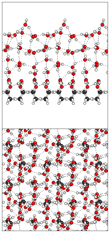 (e)
(e) 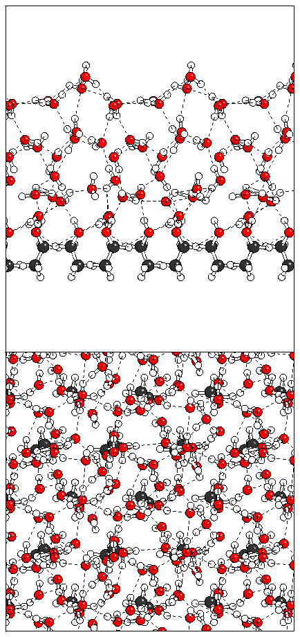
Figure 11: Relaxation of the even ferroelectric hexalayer
structure.
(a) 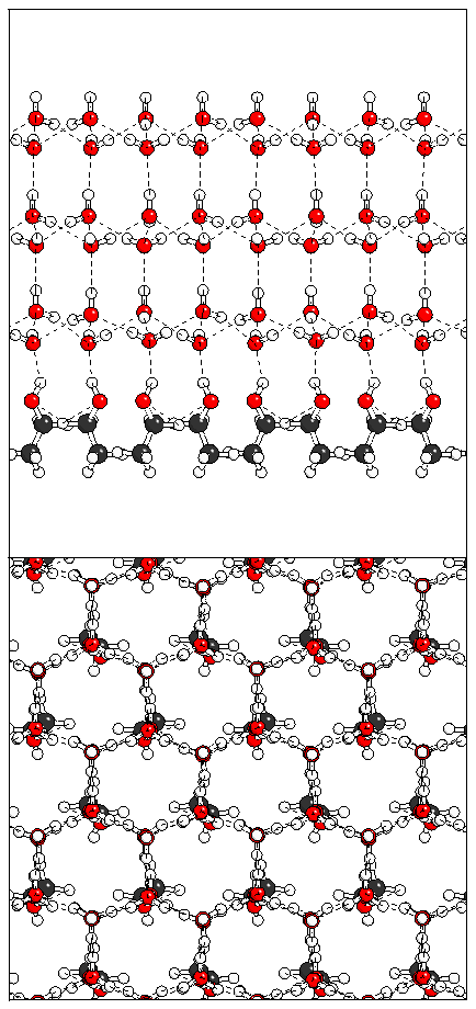 (b)
(b) 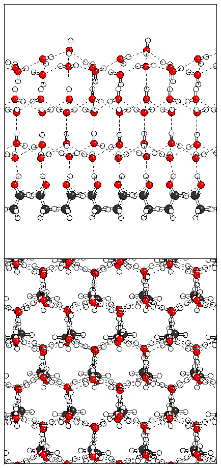 (c)
(c) 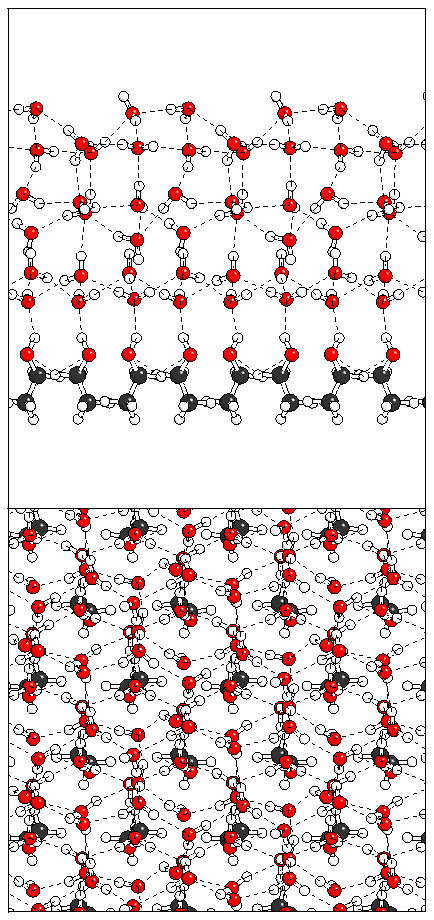 (d)
(d) 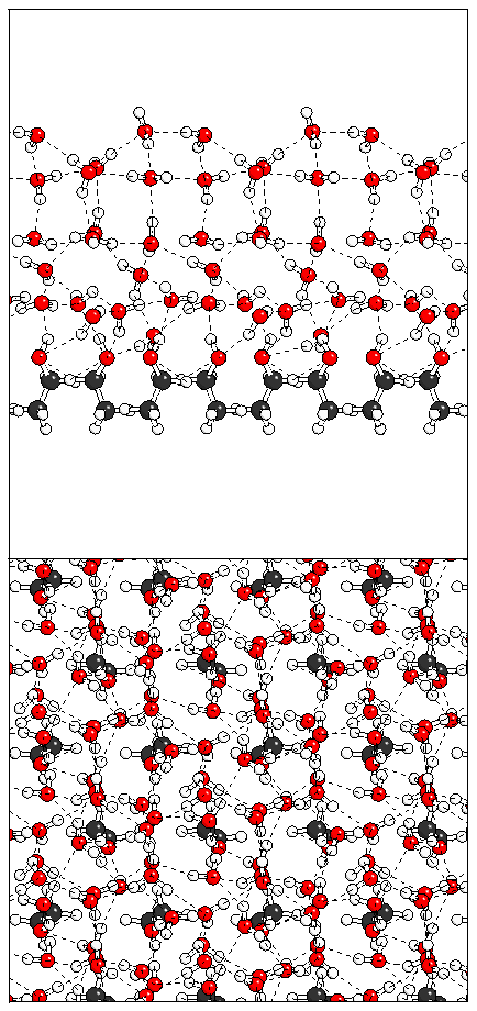
Figure 12: Relaxation of the tetralayer sandwich structure.
(a) 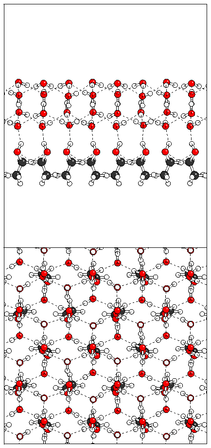 (b)
(b) 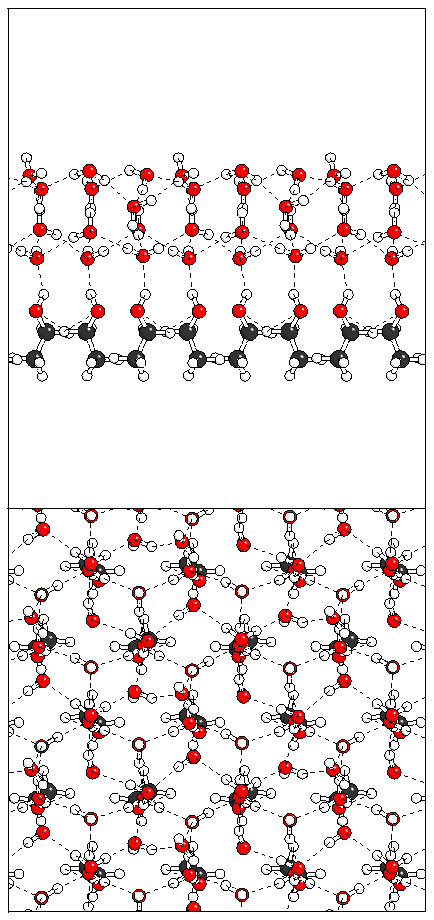 (c)
(c) 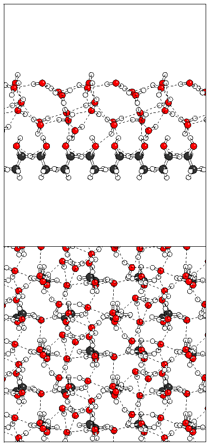
Figure 13: A minimum energy structure obtained by allowing
both bilayers to relax simultaneously.
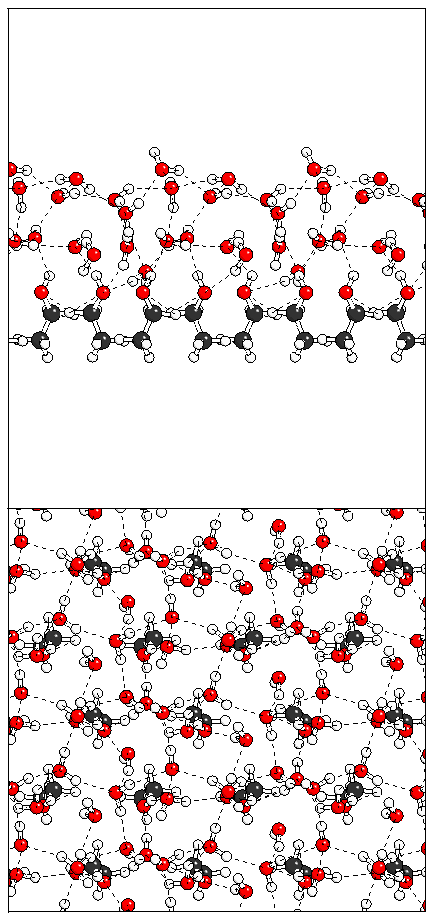
Figure 14: Relaxation of the antiferroelectric heptalayer
structure adsorbed on monolayer A.
(a) 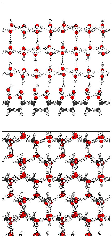 (b)
(b) 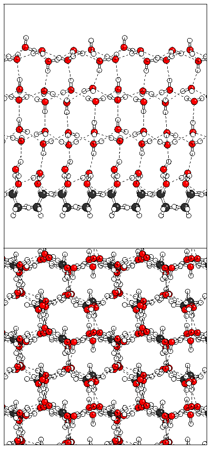 (c)
(c) 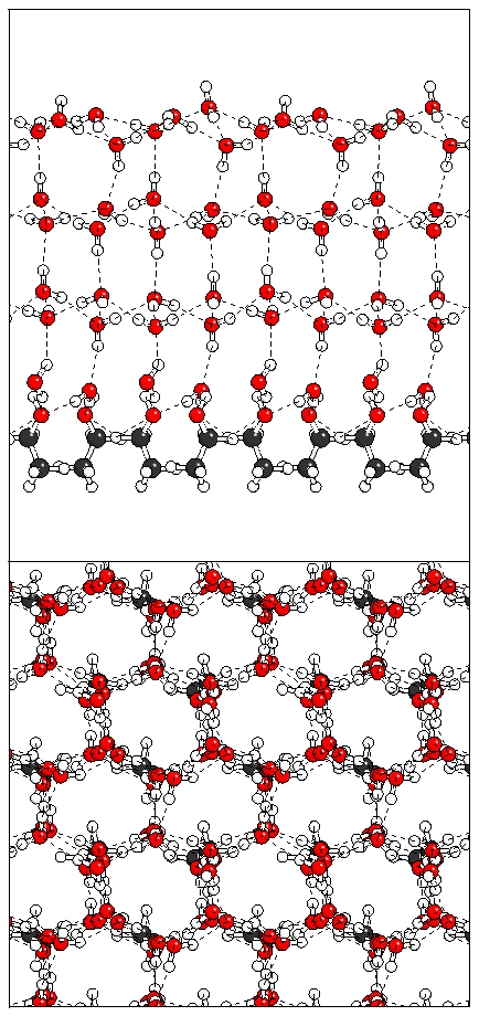 (d)
(d) 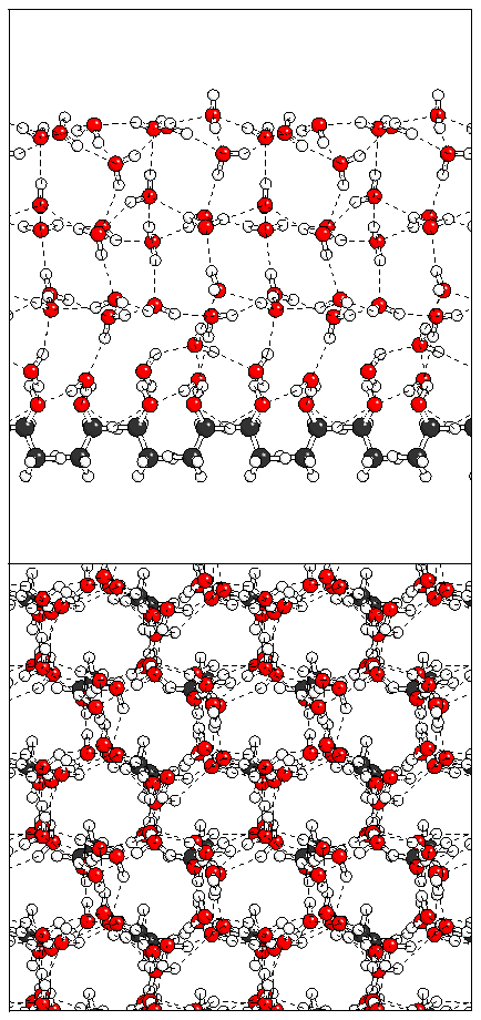 (e)
(e) 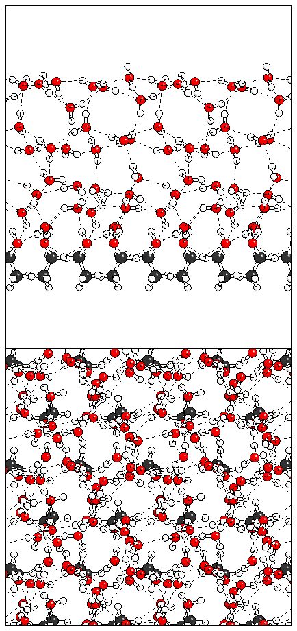
Figure 15: Relaxation of the antiferroelectric heptalayer
structure adsorbed on monolayer B.
(a) 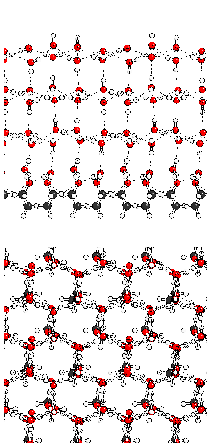 (b)
(b) 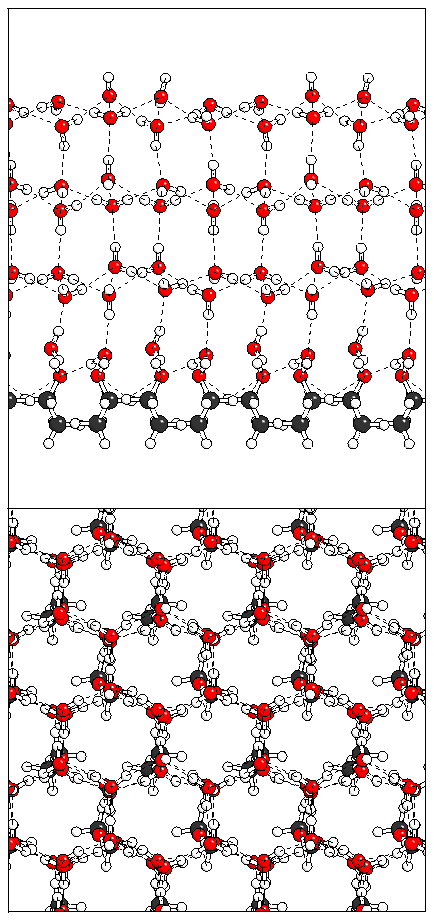 (c)
(c) 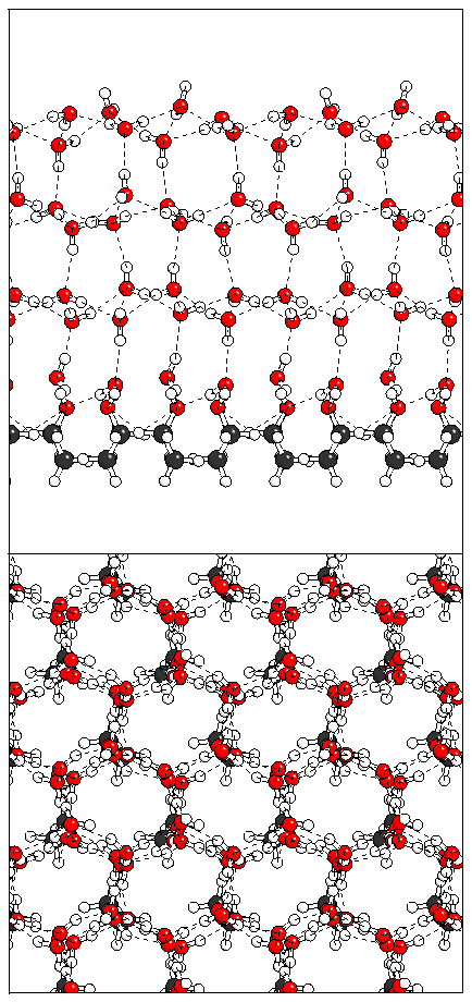 (d)
(d) 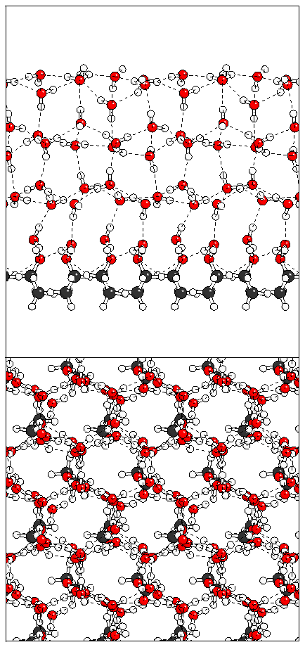 (e)
(e) 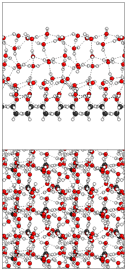
![]()